Friday, June 13, 2014

Prevailing Torque Locknuts - What "Zinc Flake" Coatings Do to Prevailing Torque

Since RoHS became effective in the European Union in 2006, there has been a global push to eliminate Cadmium (among other substances) from use in fasteners.  Cadmium plating provides a level of lubricity that helps prevent galling in all-metal locknuts, and contributes to a more consistent torque tension characteristic in threaded assemblies. 

Development of Cadmium alternatives has yielded many new coating options, including several organic and inorganic "zinc flake" coating systems which are more like paint than plating.  They are generally applied to fasteners with a "dip-spin" process where baskets of parts are immersed into a solution, then raised out of the bath and spun to prevent the coating from building up unevenly.  The wet-coated parts are usually then placed into an oven to cure the coating.  Some systems require multiple coats, sometimes of different solutions; similar in concept to primer and top coats of paint. These coating systems generally have the the following benefits:
  • High Corrosion Resistance - They generally outperform electroplated zinc with RoHS compliant chromate.
  • Controlled Coefficient of Friction - The variance in the coefficient can be less than half that of electroplated zinc.
When choosing among these finishes, there are some negative characteristics that should be considered:
  • Surface tension of the wet solutions causes build-up (excess thickness) on edges and on threads, especially for small diameter (< 1/4" or M6) nuts.  Starting a nut/bolt assembly can be affected if the coating is too thick on the threads.
  • Surface tension causes parts to stick together.  If the parts remain joined during the curing period, they will be difficult to separate, and when they are separated, the surfaces that were joined will have bare or thinly coated areas.  Again this is more of a problem with smaller parts (where the ratio of weight to surface area is small), especially flange nuts which have a large flat surface to mate with. Bare or thinly coated bearing surfaces on flange nuts may be acceptable because when assembled to a clamping position, they are not exposed.
  • There can be a puddling effect in threads of nuts where the axis of the thread is stationary and near horizontal for an extended time while the coating is curing.
Some process improvements can mitigate these effects ("thinner" solutions, direction-changing spin cycles, drops during the cure, etc.) but don't completely eliminate them, especially for very small parts.

For prevailing torque locknuts with these coatings, there are additional concerns:
  • Nylon Insert locknuts may be excluded from some of these coatings if the curing temperature is greater than the melting temperature of the nylon ring.
  • All-metal locknuts will require increasing the pitch diameter of uncoated threads to accommodate the additional thickness of these coatings.  This is more important for all-metal prevailing torque locknuts than for free-spinning nuts.  For standard 60° threads in nuts, the pitch diameter decreases by 4 units for every unit of increased coating thickness. 
  • Prevailing torque tends to increase significantly from the uncoated condition to the coated condition, and this effect must be anticipated and accommodated in the thread deflection process.  It is virtually impossible to take uncoated locknuts with compliant prevailing torque, coat them, and have the resulting prevailing torque remain compliant.
  • Since these coatings affect prevailing torque, variations in the coating thickness from part-to-part will cause corresponding additional variation in prevailing torque.

Wednesday, June 11, 2014

Prevailing Torque Locknuts - Nylon Insert Locknuts

Nylon Insert locknuts are very popular, attributable to the following characteristics:
  • in popular sizes they are relatively inexpensive and easy to find
  • starting the assembly is easy as the threads are standard until the nylon ring is encountered
  • prevailing torque is consistent and usually low within the tolerance band
  • there is no risk of galling or seizure during assembly
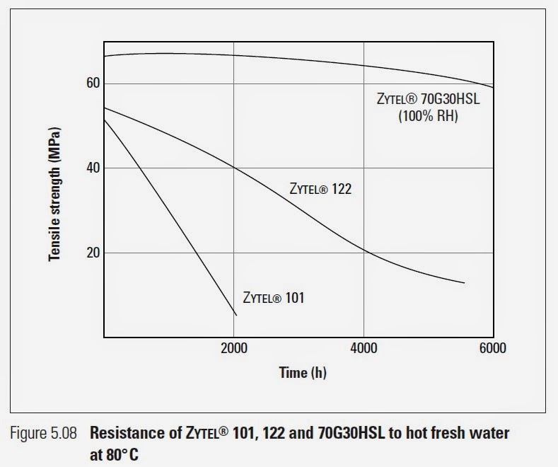
The locking element is usually made of Nylon, specifically 66 Nylon or Zytel® 101.  The rings are normally cut from sheets using dies, which makes their dimensions very consistent.  The dimensional consistency is reflected in prevailing torque consistency.

The prevailing torque is developed when the male (bolt) thread interferes with the nylon ring and forms the complimentary female thread into the ring with a combination of elastic and plastic deformation.  The outside diameter of the ring is constrained, so the inside diameter must allow this deformation without overfilling the mating thread, or the ring can be pushed out of the nut. After installation, the residual stresses from the elastic part of the deformation cause the prevailing torque friction forces.

So, all this is well understood, and well controlled, and Nylon insert locknuts are the perfect locknuts, right?  Not always.  They may not be the best option if the assembly or storage or service environment of the application includes some combination of 
  • elevated temperature
  • elevated relative humidity
  • exposure to ultraviolet radiation, including sunlight
  • extended time
  • exposure to some chemicals
The following are excerpted from DuPont™ Minlon® and Zytel® nylon resins Design Information – Module II.   I recommend browsing this guide and evaluating any application with respect to its recommendations before selecting a nylon insert locknut for the application.

"Nylons absorb moisture from the air and 66 nylon equilibrates at about 2,8% water at 50% RH and at about 8,5% at 100% RH. This plasticizes the nylon, lowering its strength and stiffness but increasing its toughness and elongation. Moisture absorption increases dimensions of 66 nylons by 0,6% at 50% RH and about 2,6% at 100% RH. The process is reversible, that is, the strength and stiffness increase and dimensions decrease as moisture content decreases. Absorption and desorption are slow processes. For example, it takes about 125 days for a 1,5 mm thick dry specimen to reach equilibrium moisture content when exposed to 50% relative humidity."

"Properties observed in weathering studies
Moulded test parts exposed outdoors to ultraviolet radiation may ultimately fail for one of the following reasons: (1) loss of strength, (2) loss of toughness or (3) change in appearance.

Changes in tensile and yield strength over the time period studied were determined using ASTM D638. Toughness was measured using a mandrel bend test, in which test bars are bent rapidly 180° around a 3,2 mm diameter steel mandrel. A tough bar has the capability of being deformed in this manner without breaking.

The relative viscosity of nylon is related to its molecular weight. Exposure of nylon that is inadequately stabilized against ultraviolet light results in surface degradation with a corresponding drop in relative viscosity or molecular weight. The interest in relative viscosity accrues from the fact that serious loss in this property is related to a comparable loss in toughness.

Change in appearance has been measured by colour difference using Adams units which are similar to National Bureau of Standards (NBS) units."

"Factors important to service life of a nylon in a chemical environment. The designer must define the specific conditions of the chemical environment before he can determine whether the probability for a successful application is good. Some of these conditions are:
  • Temperature. Depending on the specific reagent, service life can be significantly reduced by an increase in temperature. Acids and oxidizing agents are particularly harmful to nylons at higher temperatures. It is difficult to generalize on the quantitative aspects of increased temperatures although a 15° C rise in temperature will frequently reduce service life by 25–50%.
  • Chemical concentration. Chemical concentration has a bearing on service life of nylons. This is true for acids and will depend greatly upon the pH. The effect of concentration will vary from one material to another and generalizations are impossible to make.
  • Time. This is important in defining the suitability of an application in a particular reagent. Does the application involve 60 days of intermittent exposure or two years of continuous exposure?
  • Part surface to weight ratio. Here the ratio of surface area to weight is important. The greater this ratio, the more rapid the attack.
  • Stress level. Although nylons are very resistant to attack from a wide variety of chemical agents, a few inorganic salts can cause severe breakdown of nylons under stress.
Zinc chloride, for example, is especially harmful to 66 nylons such as ZYTEL® 101, but has a lesser effect on 612 nylons such as ZYTEL® 151. End-use tests should always be employed to determine the suitability of a nylon for a particular application."  


Monday, June 9, 2014

Prevailing Torque Locknuts - When They Don't Work, What Happened?

You can't be in the locknut business very long without encountering someone having problems with locknuts in their applications.  When a locknut manufacturer's registered quality system includes rigorous quality controls, their parts pass the qualification tests, and there are still problems on the customer's assembly line, what happened? The short answer is that sometimes there are misapplications of locknuts.

A free-spinning nut is relatively tolerant of assembly conditions; locknuts are sensitive to assembly conditions.  It's not reasonable to expected a locknut to work in an application simply because a free-spinning nut did.  So, what can a free-spinning nut tolerate that a locknut can't?
  • Mating part thread quality - anywhere within the standard tolerance for pitch diameter (which allows some running clearance between threads), the free-spinning nut installs the same, while the prevailing torque of a locknut will vary with the pitch diameter of the mating part.
  • Assembly speed and distance - the work of driving a locknut (prevailing torque times angle) is converted directly to heat at the points of sliding contact between the locknut and bolt.  If too much heat is created faster than it can dissipate, the temperature of the threads will rise. Especially with large diameter close clearance thread class parts, this temperature rise will cause thermal expansion, which can cause runaway torque and assembly seizure prior to achieving the desired clamping tension in the bolt. Free-spinning nuts have no prevailing torque, and so no work is converted into heat until the assembly starts to clamp, and then the angle from starting clamp to assembly complete is usually small enough to limit the heat that is generated to insignificant.
  • Nut/bolt material mismatch - for all-metal locknuts, the material properties of the locknut and the bolt should be similar, so they can share the load of the thread interference.  If one is softer/weaker than the other, the softer component will wear faster as it yields at a lower stress level.  It may not be intuitive, but the prevailing torque of a mismatched all-metal locknut assembly will decay faster than that of two softer, matched components. Since there is no thread interference for a free spinning nut, this effect does not exist with them.
  • Start thread condition - Since the threads of a free-spinning nut are not loaded until the assembly starts clamping, the only condition on the start thread of the mating part is that it can accept the ring-type GO gage for the thread specification.  For locknuts, the start thread of the mating part (bolt) should have a chamfer.  With all-metal locknuts the start thread will be loaded by the thread interference, and if the thread section is too thin, it  
    can bend or break off and contaminate the assembly to the point of seizure.  With nylon insert locknuts, the insert can be pushed out of the nut before the thread form is impressed into it. The start thread chamfer for


    locknut
     mates should be per the description in ASME B18.2.1 Hex Cap Screw Point 


“Point shall be chamfered or rounded at manufacturer’s option from approximately 0.016 in. below the minor diameter of the (bolt) thread. The first full formed thread at major diameter is located a distance no greater than 2 times the thread pitch from the end of the screw. This distance is to be determined by measuring how far the point enters into a cylindrical NOT GO major diameter ring gage (reference Gage, ASME B1.2, Page A-80).”

Most application problems resulting from a locknut replacing a free-spinning nut in an assembly can be traced back to one of these conditions.  If the condition can be removed, the assembly will be successful.


Tuesday, June 3, 2014

Prevailing Torque Locknuts - How They Work

The prevailing torque in prevailing torque locknuts comes from localized plastic deformation to an interference fit with continuous sliding during assembly.  Let's break this down.

Localized plastic deformation - Some of the starting threads need to be able to accept the mating part (bolt, say) before the prevailing torque begins.  The interference is therefore localized to not include the immediate start of the assembly.  For nylon insert locknuts, the interference is only in the nylon ring, and the metal part of the nut is free-spinning; but the interference is the entire internal circumference of the nylon ring.  For all-metal locknuts, the threads are plastically deflected such that there are points of interference (1, 2, 3, or 6 points of interference, depending on the configuration of the deflection) with the threads of the mating part.

Interference fit - the threads of a prevailing torque locknut have negative clearance (there is contact and deflection) with the mating part.

Continuous sliding - contacting thread surfaces of the locknut and bolt are sliding across each other as the nut is installed.

The normal forces that result from the interference fit have three effects:
  • They cause localized plastic deformation on the contact areas of the threads until the contact areas are large enough to support the forces (resulting point stresses are below the yield stress). This deformation occurs over a number of rotations of the locknut on the bolt, and causes the prevailing torque to "wear out".
  • They knock down the minuscule asperities on the thread surfaces to make the surfaces smoother.
  • They combine with the coefficient of friction of the surfaces to create tangential friction forces acting at the pitch diameter, which become the prevailing torque.

Prevailing Torque Decay

Because of these effects, when the assembly is behaving correctly the prevailing torque of a prevailing torque locknut is constantly decaying as the locknut is installed.


The rate of decay depends on
  • The hardness of the materials
  • The degree of interference
  • How the interference is distributed across the surface of the threads

So, at the same prevailing torque levels, softer material and/or more localized deflections will result in the prevailing torque wearing out at a higher rate.


Prevailing Torque Variation

There are several normal sources of variation in the prevailing torque of a locknut, including

- Part-to-part variations within a lot of the mating part (bolt)
  • pitch diameter
  • thread defects (nicks, dents, dings)
- Part-to-part variations within a lot of the locknut component (the nut before deflection)
  • pitch diameter
  • exterior dimensions (height, concentricity of the thread to the hex, width across flats, concentricity of the nylon ring to the thread, diameters and thickness of the nylon ring)
- Process variations
  • location of the deflection (especially relative to where the thread exits the top the locknut, for axially deflected all-metal locknuts) 
  • degree or depth of the deflection

The effect of these variations is reflected in the prevailing torque


Prevailing Torque Limits

When defining limits on prevailing torque, the normal effects of decay and variation should be considered.


A well developed deflection mechanism and deflection process can minimize the decay and variation, but they will always be present to some degree, and decay and variation controls (special nut thread tolerances, special tighter nut dimensional tolerances, special test bolts, complex process tooling, etc.) can add prohibitive expense to a process.

Prevailing Torque Locknut Testing and Qualification

In addition to inspections common to all internally threaded fasteners (nuts), prevailing torque locknuts are inspected for prevailing torque performance.  Prevailing torque is the resistance to assembling or disassembling the locknut and mating part when the assembly is not clamping (not developing tension in the mating part).  Prevailing torque performance is sensitive to a number of assembly condition variables, including:
  • Mating part characteristics (Pitch diameter, hardness, plating/finish, start thread bevel, thread surface condition)
  • Assembly Speed
  • Assembly Distance
To support the repeatability of the results, a complete inspection procedure definition will specify (control) all these quantities, because as any of the above varies, the results of the inspection will vary.

Some inspection procedures require the assembly to be driven to a specified clamping condition (torque-tension test), and to measure the drive torque required to achieve that tension.  In these instances, the bearing surface conditions (hardness, plating, hole diameter, washer diameter, washer thickness) must also be specified. Some inspection procedures require multiple installation and removal cycles to demonstrate the wear characteristics of the prevailing torque.

Also, most inspection procedures include changing conditions (initially driving prior to encountering the prevailing torque element, driving with prevailing torque through an unclamped distance toward clamping, loading to or unloading from a clamped position, driving away from a clamped position, changing direction toward clamping again, ...).  These condition changes may or may not have functional significance to a particular application, and so may or may not require concurrent torque measurement.  A complete inspection procedure definition will include the periods and points withing the procedure to measure torque. It will also specify the required accuracy of the torque measurements, and the required accuracy of the control variables (angular position, clamp tension, etc.) that trigger the measurements.

A proper prevailing torque inspection presents the following difficulties
  • Complexity - a number of conditions must be controlled and/or must trigger measurements.
  • Expense - relative to simple dimensional inspections, the prevailing torque inspection takes a long time on expensive equipment; the test is destructive and consumes a locknut and usually a mating part.
  • Relevance - If the assembly conditions of the inspections are different than the assembly conditions of the application, the inspections results may not be a good predictor of the success of the application assembly.
Industry standards are a great resource for qualification test procedures, with the following caveat:  If your application assembly conditions are different than the standard test conditions, "your mileage may vary".

Friday, May 23, 2014

Prevailing Torque Locknuts - What to ask for (Part 2)

Sometimes there is no standard locknut that will satisfy the requirements of an application.  In these instances, a locknut fulfilling special requirements should be defined in a controlled document that specifies the characteristics listed in Part 1.  That requirements document (an engineering drawing, for example) should reference standards for as many characteristics as possible.  Then for those characteristics that have non-standard requirements, the limits and tolerances assigned to those characteristics should be evaluated by a locknut expert for feasibility and cost/benefit. 
The requirements document should be referenced in any Request For Quote (RFQ) inquiring about the locknut.

While the standards are good examples of locknut specification, I have encountered a number of common bad locknut requirements specifications.  I'll try to explain what makes a specification good or bad.  A good specification can be related directly to fit, form, or function in an application.  Examples are

  • Thread Start (Go Gauge) Minimum - Ensures that the locknut can be started in the assembly without cross threading.  The thread deflection that creates the prevailing torque occasionally can impact the starting threads, so this is an important characteristic.
  • Installation Torque Maximum - Limiting the installation torque allows an assembly drive tool to be selected that will accomplish the assembly.
  • Removal Torque Minimum - Ensures that a minimum prevailing torque will be working to prevent dissassembly.
  • Bearing Diameter Minimum and Countersink Diameter Maximum - Limit how small the bearing surface  can be.  The axial load stress and bearing surface friction both depend on a functional bearing surface area to make the assembly successful.
A bad locknut specification does not relate directly to fit, form, or function.  I generally see bad specifications that attempt to relate a dimension to prevailing torque performance.  The motivation is to replace an expensive, destructive performance test with a simple dimensional measurement.  In theory, if it measures correctly, it will perform correctly.  The problem is that prevailing torque performance is sensitive to several factors in combination, including some dimensions, and is more sensitive to some dimensions than others.  Some bad locknut specifications are
  • Minor Diameter at the Thread Deflection - this is sometimes specified with Go/NoGo pin gauges.  The problem with this specification is that the action of the deflected threads is applied at  the Pitch Diameter, not the Minor Diameter.  The standard tolerance for the Minor Diameter can be large relative to how much the pitch diameter is deflected to achieve prevailing torque, and the pitch diameter is not tightly correlated to the Minor Diameter.  From lot-to-lot, there will be some parts with acceptable prevailing torque that fail this inspection (false positives), and some parts with non-compliant torque that pass it (false negatives).
  • "Crimp" Deflection -   The standard tolerance for Width Across Flats can be large relative to how much the pitch diameter is deflected to achieve prevailing torque,  and the pitch diameter is not tightly correlated to Width Across Flats.  From lot-to-lot, there will be some parts with acceptable prevailing torque that fail this inspection (false positives), and some parts with non-compliant torque that pass it (false negatives).
Another class of bad locknut specification is performance characteristics without inspection methods.  A good specification will define the inspection procedure and conditions, including
  • drive speed and distance
  • mating part (test bolt), including material, hardness, finish, and thread specification
  • when to record measurements within the assembly and removal.

There are also bad specifications that put requirements on quantities that are not controllable, like coefficient of friction.  If the specification includes material hardness and finish (including lubricant), the ability of the manufacturer to control coefficient of friction is severely restricted; you get what you get.

Finally, the way that deflected thread locknuts work (localized plastic deformation to an interference fit with sliding), the associated dimensional and material tolerances, and some variables like the proximity of the deflection to where the thread exits the locknut all play into common locknut behaviors

  • Prevailing torque degrades (wears out) with installation/removal rotations
  • There is significant variation (scatter) in prevailing torque from part to part

In light of this, using standard manufacturing processes and materials to produce deflected thread locknuts, it is not economically realistic to 
  • specify a minimum first removal torque that is more than 2.5 times higher than the standard first removal torque for the same size and material. 
  • specify a maximum installation torque that is smaller than 4 times the minimum first removal torque, as measured by the process and equipment described in ASME B18.16.6.
  • These rule-of-thumb ratios get worse as the difference from standard prevailing torque increases (light torque or heavy torque).

Prevailing Torque Locknuts - What to ask for (Part 1)

There are several characteristics of prevailing torque locknuts that should be included in a complete specification.  For many of these characteristics, it is equally important to define how the characteristic is measured.  National and international standards are good examples of complete definitions, and whenever possible should be referenced or mimicked when specifying these parts for the following reasons:
  • Compatibility with standard mating parts
  • Predictable performance
  • Generally more available and less expensive 
A complete prevailing torque locknut specification will include the following characteristics:
  • Threads
    • thread form
    • nominal diameter
    • thread pitch
    • clearance class or special minor diameter and pitch diameter
    • go-gauge insertion minimum prior to encountering the prevailing torque element
  • Material (chemical composition)
  • Dimensions
    • Wrenching Dimensions
      • Configuration (Square, Hex, etc.)
      • Width Across Flats
      • Width Across Corners
      • Wrenching Height
    • Bearing Dimensions
      • Bearing Circle Diameter
      • Thread Countersink Diameter
      • Flange Thickness (if applicable)
      • Perpendicularity of the Thread Axis to the Bearing Surface
      • Concentricity of the Thread Axis to the Bearing Surface
    • Envelope Dimensions
      • Overall Thickness
      • Flange Diameter
  • Finish (coating or plating)
  • Mechanical Performance
    • Through Hardness
    • Load Capacity (Proof Load)
    • Prevailing Torque
      • Installation Maximum
      • Removal Minimum 
Sometimes additional characteristics should be specified, depending on the application:
  • Torque vs. Tension
  • Breakaway Torque
  • Vibration
  • Performance at Temperature 

Each of these characteristics can be associated directly to functionality in an application, and inspecting them can be helpful in qualifying parts as acceptable.  There are risks and costs associated with specifying characteristics that are not listed above, or not specifying any of those that are listed above.